Circuit Diagram Vs Single Line Diagram Schematics provide a detailed view of the complete system and can be used to debug and develop the circuit design On the other hand single line diagrams provide a simple overview of the entire power distribution
Single line diagrams SLDs are simplified graphic representations of the circuitry in a building while schematic diagrams provide more detailed information and are often used to One line diagrams are used when information about a circuit is required but detail of the actual wire connections and operation of the circuit are not 2 Line Diagrams A line ladder diagram
Circuit Diagram Vs Single Line Diagram

Circuit Diagram Vs Single Line Diagram
https://i.ytimg.com/vi/_DYWE6rVi44/maxresdefault.jpg

Computer Circuit Diagram On Craiyon
https://pics.craiyon.com/2023-09-20/030f894b7aa84da09a880baaaed4aa8a.webp

Michelle JeeshanYakub
https://media-cldnry.s-nbcnews.com/image/upload/rockcms/2023-03/michelle-williams-kids-zz-230307-4a951f.jpg
In today s ever evolving technology landscape the terms schematic diagram and single line often get used interchangeably But what exactly is the difference between these two diagrams A schematic diagram is a visual In a single line electrical diagram each transmission or distribution power line appears as a single line on the page rather than as three or four lines showing individual conductors in a three phase AC circuit This condenses the space
As an electrical engineer deciphering electrical drawings is a fundamental skill Two of the most commonly encountered drawings are single line diagrams SLDs and schematics While both In power engineering a single line diagram SLD also sometimes called one line diagram is a simplest symbolic representation of an electric power system
More picture related to Circuit Diagram Vs Single Line Diagram

Circuit Diagram Electromagnetic Induction Knowledge Cycle
https://knowledgecycle.in/wp-content/uploads/2023/05/photo_2023-05-11_08-24-56.jpg
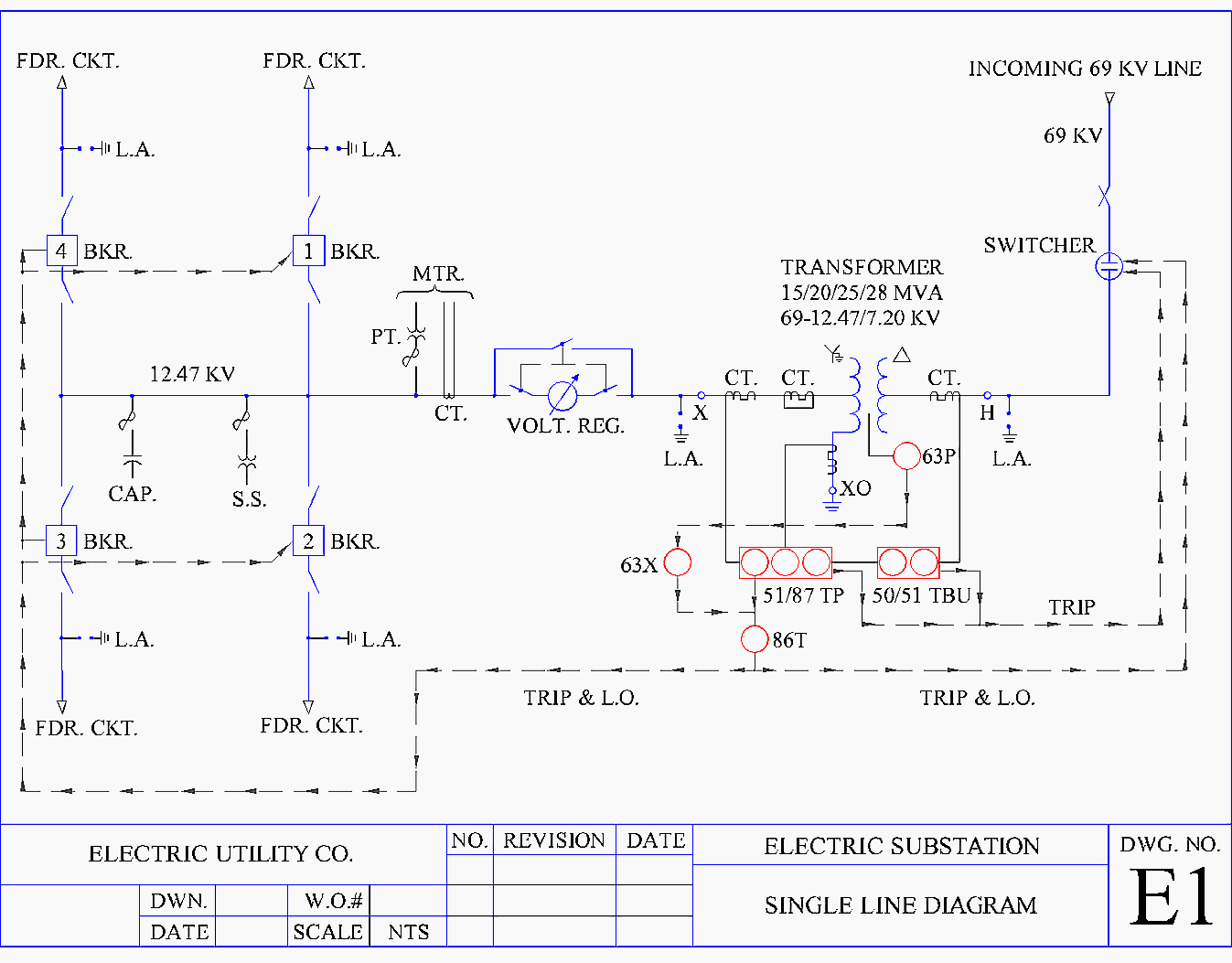
Single Line Diagram Symbols
https://electrical-engineering-portal.com/wp-content/uploads/2018/03/example-single-line-diagram-a.png

Simple Light Switch Diagram
http://2.bp.blogspot.com/-k0l5WGQ-jhY/URiQeH29PmI/AAAAAAAAAp0/veWcB5rhtu4/s1600/How+to+control+each+lamp+by+separately+switch+in+parallel+lighting+circuit...httpelectricaltechnology1.blogspot.com.jpg
Single line diagrams provide a simplified representation of electrical circuits and do not represent the precise electrical connections Single line diagrams typically use a single line to represent the electrical components and connections In short single line diagrams provide a basic overview of an electrical system while schematics go into more detail Both are necessary depending on the situation and can be combined together to create an even
This means each transmission or distribution power line appears as a single line on the page rather than as three or four lines showing individual conductors in a three phase We use Single Line to describe drawings that show cables and connection or junction boxes They have cable ID wire ID and junction box ID They do not show

SINGLE LINE DIAGRAM Ptittipatt 53 PDF
https://online.pubhtml5.com/qwdb/uoyd/files/large/53.jpg
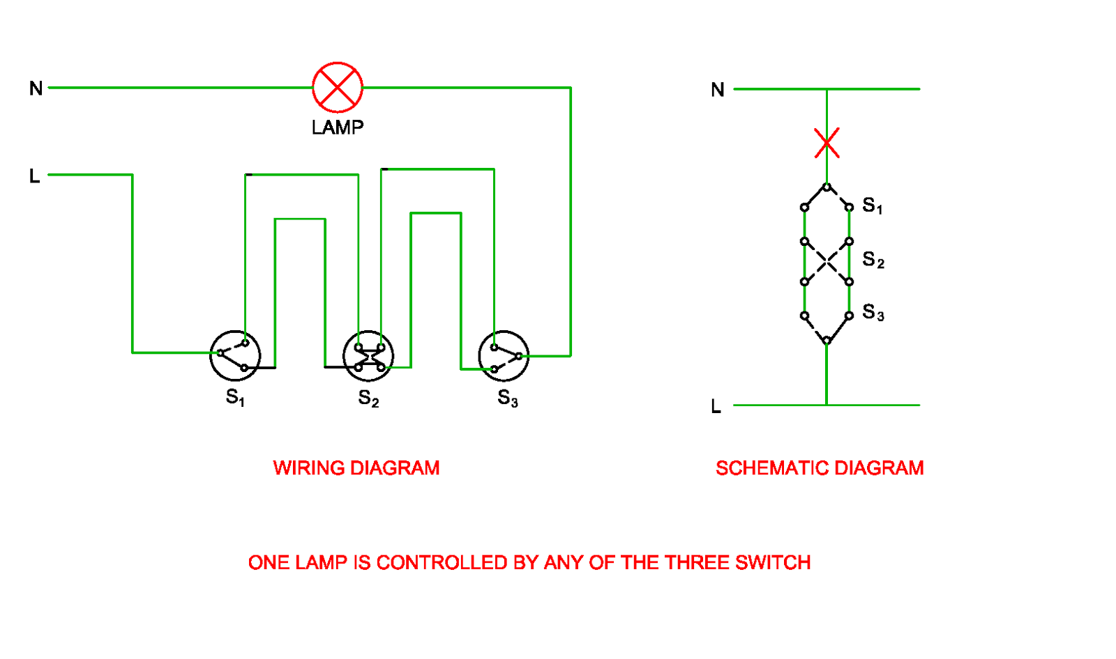
Schematic Diagram Of Switch
https://4.bp.blogspot.com/-VNO9lGJPy90/WNJj3Gp5aVI/AAAAAAAAAHg/pPt1OZi6NZgf_5tM585ic7vdUtUnu_dpgCLcB/s1600/One%2Blamp%2Bis%2Bcontrolled%2Bby%2Bthree%2Bswitch.png

https://www.circuitdiagram.co › differenc…
Schematics provide a detailed view of the complete system and can be used to debug and develop the circuit design On the other hand single line diagrams provide a simple overview of the entire power distribution

https://www.circuitdiagram.co › single-line-diagram-vs-schematic
Single line diagrams SLDs are simplified graphic representations of the circuitry in a building while schematic diagrams provide more detailed information and are often used to

How To Read European Electrical Schematics Circuit Diagram

SINGLE LINE DIAGRAM Ptittipatt 53 PDF

Single Line Diagram Electrical House Wiring Wiring Diagram
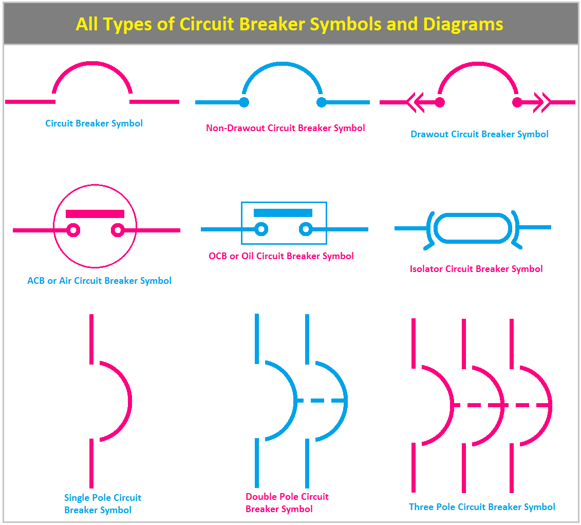
Rcbo Schematic Symbol How To Wire 1 phase Split Load Consume

Schematic Diagram Surge Protection Surge Protector Circuit D
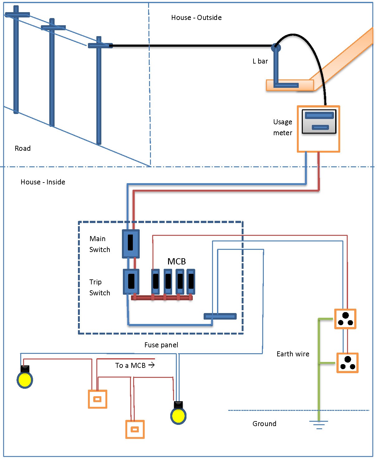
Residential Electrical Circuit Diagram

Residential Electrical Circuit Diagram

Dna Vs Rna Venn Diagram
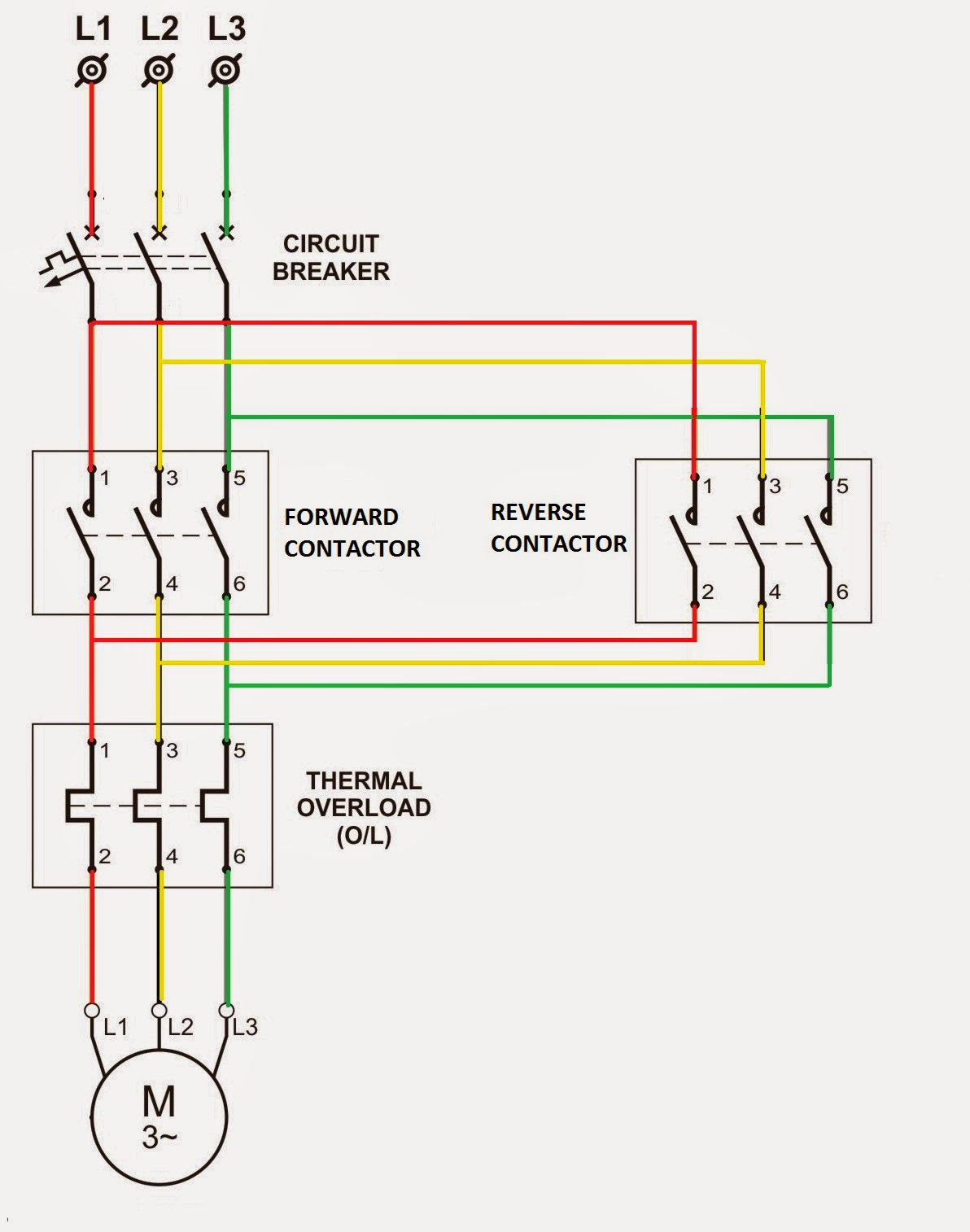
Relay Circuit Diagram And Operation

Dol Starter Power Circuit Diagram What Is Motor Starter Typ
Circuit Diagram Vs Single Line Diagram - The main difference between a one line diagram and a schematic diagram is the level of detail provided One line diagrams are designed to be quick and easy to understand