Control System Block Diagram Reduction Problems Windows key or Ctrl Esc Open Start menu Windows key X Open the secret Start menu Windows key T Cycle through the apps including pinned apps on the taskbar
A common implementation of cascade control is where a flow controller receives a setpoint from some other process controller pressure temperature level analytical etc fluid flow being In an industrial process set points and control variables can be easily and centrally maintained and controlled as part of the material master data Even customer order specific
Control System Block Diagram Reduction Problems

Control System Block Diagram Reduction Problems
https://i.ytimg.com/vi/5dJCEiGrJkE/maxresdefault.jpg

Block Diagram Reduction Problems And Solutions YouTube
https://i.ytimg.com/vi/ekAK9VizaNs/maxresdefault.jpg

Block Diagram Reduction Conceptual Questions 9 Control Systems
https://i.ytimg.com/vi/chwIDi1qKSM/maxresdefault.jpg
This article will go deeper into some control panel design concepts focusing on standards and regulations and some of the industry s best practices including NFPA 70 and If you are interested in more content about electrical power control systems check out these calculators Power Unit Conversion Calculator Energy Unit Conversion Calculator Related
Protective relay functions are typically represented in single line electrical diagrams as circles with the ANSI IEEE number code specifying each function This is analogous to ISA standard This average voltage provides an equivalent lower power while still maintaining full voltage for the on state duration of the pulse Two key parameters control the PWM signal
More picture related to Control System Block Diagram Reduction Problems

Block Diagrams Reduction Part 2 Examples 1 7 Control Systems
https://i.ytimg.com/vi/q4BzhpyiQmQ/maxresdefault.jpg

Block Diagram Reduction Problems In Control System Engineering
https://i.ytimg.com/vi/jvNwdfJk6rI/maxresdefault.jpg

Block Diagram Reduction Problems Control System Engineering
https://i.ytimg.com/vi/rxea1jiCwLw/maxresdefault.jpg
The control signal for this valve is a 3 to 15 PSI pneumatic signal coming from either an I P transducer or a pneumatic controller neither one shown in the illustration This control signal Here two differential relays control the tripping of circuit breakers ANSI IEEE function 52 at each end of the transmission line The current at each end of the line is monitored by current
[desc-10] [desc-11]

Block Diagram Reduction Problems Control System Engineering
https://i.ytimg.com/vi/Uyt9lycTQ-Q/maxresdefault.jpg

Block Diagram Reduction In Control Systems YouTube
https://i.ytimg.com/vi/_blT0wrdJ4M/maxresdefault.jpg

https://answers.microsoft.com › en-us › windows › forum › all › ...
Windows key or Ctrl Esc Open Start menu Windows key X Open the secret Start menu Windows key T Cycle through the apps including pinned apps on the taskbar

https://control.com › textbook › basic-process-control-strategies › cascad…
A common implementation of cascade control is where a flow controller receives a setpoint from some other process controller pressure temperature level analytical etc fluid flow being

Block Diagram Reduction Techniques And Shortcuts In Control Systems

Block Diagram Reduction Problems Control System Engineering
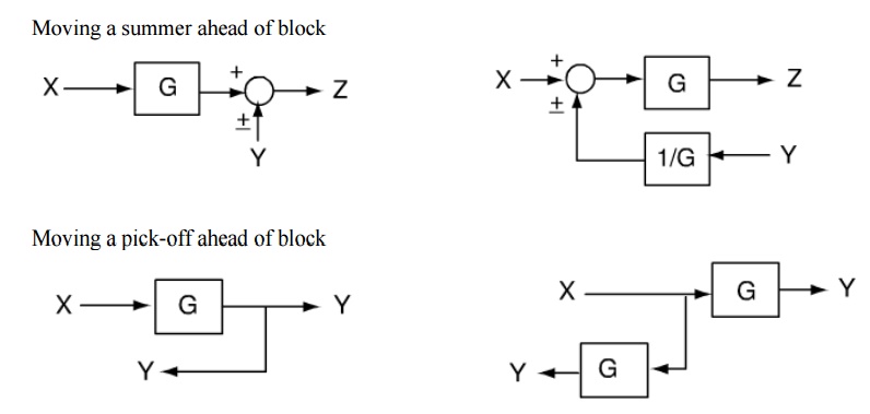
Block Diagram Reduction Techniques Transfer Function
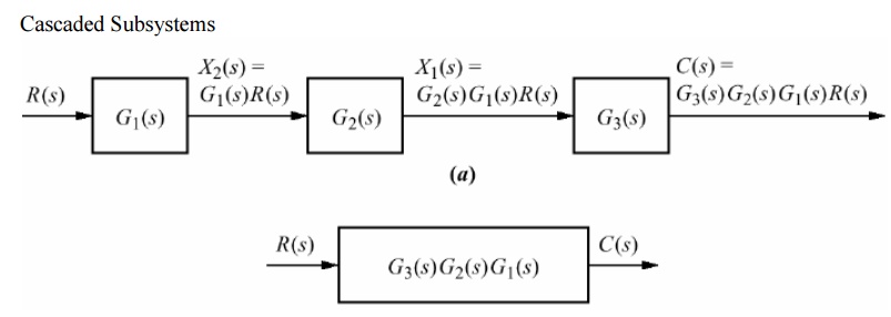
Block Diagram Reduction Techniques Transfer Function
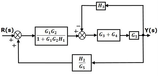
Biblioteca Troncal Muelle Regularmente Control System Block Diagram

Block Diagram Reduction Solved Problems

Block Diagram Reduction Solved Problems
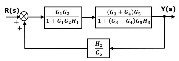
Escuela Primaria Blanco Su ter Block Diagram Algebra Examples Campa a
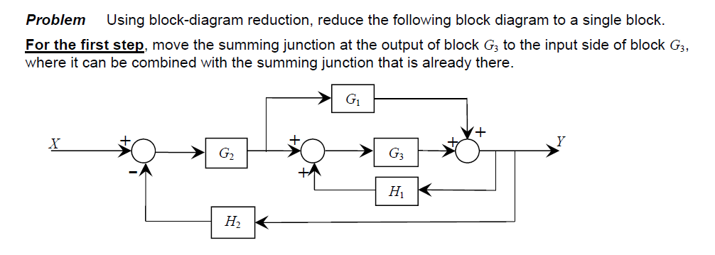
Reducing Block Diagram
Block Diagram Reduction Control System
Control System Block Diagram Reduction Problems - This average voltage provides an equivalent lower power while still maintaining full voltage for the on state duration of the pulse Two key parameters control the PWM signal